


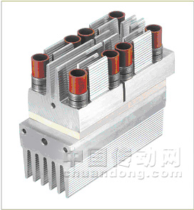
圖一:反平行可控硅模塊SEMiSTART設(shè)計(jì)專用于軟啟動(dòng)裝置
在線直接起動(dòng)器
三相感應(yīng)電機(jī)(異步電機(jī))在線直接啟動(dòng)需要一個(gè)很高的電動(dòng)機(jī)啟動(dòng)力矩及啟動(dòng)電流。高的電動(dòng)機(jī)啟動(dòng)力矩可以導(dǎo)致機(jī)械損傷;例如,將會(huì)撕破三相感應(yīng)電機(jī)帶動(dòng)的傳送帶。高啟動(dòng)電流可以導(dǎo)致網(wǎng)格內(nèi)的電壓尖脈沖。電動(dòng)機(jī)越大這種影響也越大,為了防止不希望的損傷,在啟動(dòng)階段感應(yīng)電機(jī)的電壓是受到控制的,這意味著啟動(dòng)電流和啟動(dòng)力矩可以受到限制(見(jiàn)圖二)。
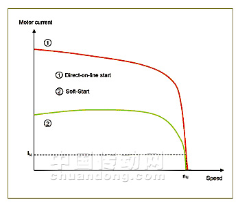
圖二:直接在線啟動(dòng)和軟啟動(dòng)電動(dòng)機(jī)電流
星形三角形起動(dòng)器
星形三角形起動(dòng)器(即星/三角轉(zhuǎn)換起動(dòng)器)是一個(gè)簡(jiǎn)單的方案,當(dāng)電動(dòng)機(jī)提高運(yùn)轉(zhuǎn)速度時(shí)電動(dòng)機(jī)定子繞組以星形接法連接,一旦電動(dòng)機(jī)達(dá)到了額定轉(zhuǎn)速,繞組即以三角接法連接,以星形連接的方法啟動(dòng)的作用是:在電動(dòng)機(jī)達(dá)到正常轉(zhuǎn)速的過(guò)程中經(jīng)過(guò)每個(gè)定子繞組的電壓是正常經(jīng)過(guò)定子繞組電壓的三分之一。從星形接法轉(zhuǎn)到三角形接法通常是通過(guò)一個(gè)機(jī)械接觸器來(lái)完成的。然而,因?yàn)橹挥袃煞N交換連接法(星形接法和三角形接法),控制也就不是一個(gè)很適當(dāng)?shù)姆椒?,此外,機(jī)械接觸器由于火花容易造成磨損而需要替換,這種起動(dòng)器控制維修率很高。
軟起動(dòng)器
在啟動(dòng)階段控制感應(yīng)電機(jī)的電壓需要一個(gè)軟啟動(dòng)裝置(軟啟動(dòng)器)。軟啟動(dòng)器需要一個(gè)可控硅來(lái)控制電壓。(見(jiàn)圖三)
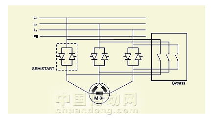
圖三:軟啟動(dòng)原理示范
反平行可控硅在電動(dòng)機(jī)繞組和網(wǎng)格間串聯(lián),在加速到正常運(yùn)行速度期間(斜坡啟動(dòng))經(jīng)過(guò)電動(dòng)機(jī)繞組的電壓是相位控制的。觸發(fā)何時(shí)延遲意味著起動(dòng)力矩和啟動(dòng)電流可以設(shè)定到期望值。軟啟動(dòng)控制的領(lǐng)一個(gè)優(yōu)點(diǎn)在于啟動(dòng)時(shí)間也可以得到控制。
通過(guò)可控硅的電流在半導(dǎo)體中產(chǎn)生功率消耗,這就使得半導(dǎo)體受熱,然后半導(dǎo)體需要冷卻,為了阻止斜坡啟動(dòng)階段后功率的進(jìn)一步消耗,半導(dǎo)體通過(guò)一個(gè)機(jī)械開(kāi)關(guān)(接觸器)旁通。旁通開(kāi)關(guān)可以相對(duì)較小,因?yàn)闊o(wú)需開(kāi)關(guān)大電流負(fù)荷。系統(tǒng)已經(jīng)達(dá)到了額定運(yùn)行速度,無(wú)需通過(guò)旁落開(kāi)關(guān)轉(zhuǎn)換更大的電壓降落,唯一的電壓降落是來(lái)自軟啟動(dòng)器的構(gòu)造設(shè)計(jì)和通過(guò)可控硅的觸發(fā)。這即意味著無(wú)需轉(zhuǎn)換更大的電流負(fù)載,這就使得軟啟動(dòng)器維護(hù)率非常低。
半導(dǎo)體要求
為了確保軟啟動(dòng)器同時(shí)具有緊湊和高性價(jià)比的特性,而不降低其可靠性,軟啟動(dòng)器中的半導(dǎo)體需要滿足重要的要求。
即使當(dāng)軟啟動(dòng)器在啟動(dòng)階段運(yùn)用的啟動(dòng)電流是額定電流的幾倍(3-5倍),在大規(guī)模系統(tǒng)中,啟動(dòng)電流峰值通常達(dá)到好幾千安培,因此半導(dǎo)體必需能夠帶動(dòng)這樣的高啟動(dòng)電流,同時(shí),軟啟動(dòng)器必需經(jīng)濟(jì)實(shí)惠并且盡可能簡(jiǎn)潔,因此,所用的半導(dǎo)體必需盡可能?。òㄉ崞?
出于成本的原因,在實(shí)際中運(yùn)用可控硅元件,其額定電流遠(yuǎn)遠(yuǎn)低于大型系統(tǒng)啟動(dòng)電流。這就是可控硅芯片在短暫的啟動(dòng)階段充分加熱的原因,即:從T斜坡啟動(dòng)溫度40°C到130°C,芯片溫度相差90K。如果系統(tǒng)每天轉(zhuǎn)換三次,每天8小時(shí),那么十年后負(fù)載總變化將達(dá)到87,600小時(shí)。可控硅必需能夠在數(shù)十年內(nèi)承受啟動(dòng)階段的過(guò)載電流。
直到現(xiàn)在,軟啟動(dòng)生產(chǎn)商在為其設(shè)備尋找適宜的半導(dǎo)體方面還存在困難。這也是反平行可控硅模塊SEMiSTART可插足的市場(chǎng),因?yàn)樵撃K是專為軟啟動(dòng)裝置研發(fā)。
安裝和連接技術(shù)
組裝和連接硅片有多種不同的方法。在許多模塊中,用單面模塊冷卻將硅片同時(shí)焊接在陰極和陽(yáng)極。(見(jiàn)圖四)
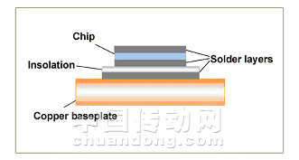
圖四:焊接模塊原理
積聚在模塊中的熱量通過(guò)底盤(單面冷卻)分散到散熱片。一個(gè)特殊的問(wèn)題是可控硅模塊單個(gè)元件具有不同的熱膨脹系數(shù)。在帶有焊接頭的模塊中,可控硅芯片,焊料和銅(主端子)有不同的膨脹系數(shù)。
隨著時(shí)間推移,由于負(fù)荷循環(huán)操作,不同的膨脹系數(shù)導(dǎo)致連接芯片和銅端子的焊料疲勞,結(jié)果出現(xiàn)焊料分層,即:焊料層出現(xiàn)細(xì)裂紋。焊料疲勞裂紋又導(dǎo)致熱電阻增加,反過(guò)來(lái),熱電阻的增加導(dǎo)致了芯片溫度升高,從而最終導(dǎo)致芯片失效。事實(shí)上,焊接模塊中芯片失效不常發(fā)生。
模塊是基于壓力接點(diǎn)技術(shù)的,與之相反的是,芯片通過(guò)接點(diǎn)壓力連接在主端子間,在這些模塊中,主端子間不焊接芯片,而需要一個(gè)非常高的接點(diǎn)壓力以固定主端子間的芯片。事實(shí)上,在高功率負(fù)荷應(yīng)用中(額定電流>200A),運(yùn)用壓力接點(diǎn)技術(shù)連接的元件由于沒(méi)有運(yùn)用焊接,其負(fù)荷循環(huán)能力連接相對(duì)較高。
這就是賽米控推薦在大額定電流的軟啟動(dòng)裝置中使用壓力接點(diǎn)元件的原因。而在SEMiSTART中也使用了壓力接點(diǎn)技術(shù)。(見(jiàn)圖五)
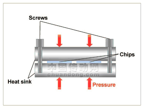
圖五:SEMiSTART模塊中所用壓力接點(diǎn)技術(shù)
SEMiSTART模塊中在兩個(gè)散熱片間模壓可控硅芯片
這種安裝和連接類型不包括焊接層,這也是SEMiSTART模塊擁有卓越的負(fù)荷循環(huán)能力的原因,也正是由此使其擁有長(zhǎng)效的使用壽命。
散熱片選擇最佳尺寸以適合芯片的尺寸和軟啟動(dòng)裝置,這就使得模塊非常簡(jiǎn)潔小巧,可控硅和散熱片間的總熱阻遠(yuǎn)低于其他傳統(tǒng)元件總熱阻。因?yàn)樾酒苯幽涸谏崞g,同時(shí)受到兩面冷卻,熱阻就非常低。另外一個(gè)優(yōu)勢(shì)就是安裝SEMiSTART模塊非常方便,與安裝模塊一樣,在安裝塑封可控硅,時(shí)也無(wú)需特殊夾具,另外,在安裝模塊時(shí)也無(wú)需熱膠。
當(dāng)然,SEMiSTART模塊可以應(yīng)用于其他方面,如保護(hù)電路。SEMiSTART模塊有三種不同尺寸和五種不同的電流等級(jí)。二十秒鐘最大電流時(shí)間(斜坡啟動(dòng)時(shí)間)電流在500A – 3000A間??煽毓钄鄳B(tài)電壓最大1800V。
結(jié)論
未來(lái)幾年內(nèi),由于這些軟啟動(dòng)控制元件方案較傳統(tǒng)元件更為突出,軟啟動(dòng)市場(chǎng)將繼續(xù)發(fā)展,由于使用了雙面可控硅芯片冷卻及其緊湊的設(shè)計(jì),軟啟動(dòng)器反平行可控硅模塊SEMISTART較傳統(tǒng)模塊產(chǎn)生一半的熱阻。因此會(huì)出現(xiàn)短期的較高過(guò)電流,此外,由于使用了壓力接點(diǎn)技術(shù),這些模塊具有高度可靠性。
original text
[COLOR=#708090][b]POWER ELECTRONICS EUROPE
MOTOR CONTROL
Soft-Start Control of Electric Motors
Soft-Start Control of Electric Motors[/b]
Figure 1:The anti-parallel thyristor module SEMiSTART is designed specifically for use in soft-start devices
For a three-phase induction motor direct on-line start involves a very high motor starting torque and a very high starting current. Semiconductors in soft-start devices must be extremely robust to resist considerable chip temperature changes and must demonstrate very good load cycle capability. The antiparallel thyristor module SEMISTART for soft-starters provides half the internal thermal impedance of conventional components, thanks to double-sided thyristor chip cooling and thus, ensures high over-current capability for the starting period. Norbert Schafer and Ralf Herrmann, SEMIKRON, Nuremberg, Germany
The anti-parallel thyristor module SEMiSTART (Figure 1), designed specifically for use in soft-start devices, provides half the internal thermal impedance of conventional components in modular designs, thanks to double-sided thyristor chip cooling. This compact module also uses proven pressure contact technology. In practice, three different types of motor starter control are used which are described in the following.
Direct on-line starters
For a three-phase induction motor (asynchronous motor), direct on-line start involves a very high motor starting torque and a very high starting current. The high motor starting torque can lead to mechanical damage; for instance, the conveyor belt driven by the three-phase induction motor may tear. The high starting current can also result in voltage spikes in the grid. The larger the motor, the more serious the effects. To combat such undesired effects, the voltage applied to the induction motor during the start-up phase is controlled. This means that the starting current and, consequently, the starting torque can be limited (see Figure 2).
Figure 2: Motor current at direct on-line start and with soft start
Star-delta starters
A simple solution is the star-delta starte (also known as the wye-delta starter). Here, the motor stator windings are connected in star (or wye) connection as the motor accelerates up to its running speed; once the motor reaches near rated speed, the windings are connected in delta. The effect of starting in star connection is that the voltage across each stator winding during the build-up to normal running speed is 1/3 of the normal. The changeover from star to delta connection is normally done using a mechanical contactor. As, however, there are only 2 switch connections (star and delta), controlling‘ is not a particularly appropriate term in this case. Moreover, this type of starter ‘control‘ is not low- maintenance, as the mechanical contactors are prone to wear caused by sparking and need to be replaced.
Soft-starters
To control the voltage applied to the induction motor during the start-up phase, a soft-start device (soft starter), is needed. In soft starters, thyristors are used for voltage control (see Figure 3).
Figure 3:Principle schematic of a soft starter
Two anti-parallel thyristors are connected in series between the motor windings and the grid. During the run-up to normal running speed (ramp-up), the voltage across the motor windings is the controlled by way of phase control. Depending on when the thyristors are fired (trigger delay angle a), this means that the starting torque and the starting current can be set to desired values. A
further advantage of soft-start control is that the starting time can also be controlled.
The current flowing through the thyristors produces power dissipation in the semiconductors. This power dissipation heats up the semiconductors, which then have to be cooled. To prevent further power dissipation in the semiconductors after the ramp-up phase the semiconductors are bypassed by a mechanical switch (mechanical contactor). This bypass switch can be relatively small since it does not have to switch large loads. The system has already reached normal running speed, no large voltage drop that has to be switched by the contacts of the bypass switch occurs. The only voltage drop is that resulting from the mechanical design and that across the fired thyristors. This means that no large loads are being switched, which is why soft-starters are low- maintenance devices.
Semiconductor requirements
To ensure that a soft-starter is both compact and cost-efficient without compromising reliability, the semiconductors used in a soft-starter must meet a number of important requirements.
Even when a soft-starter is used the starting current during the starting phase of a drive system is still several times larger than the rated current (3-5 times higher). In large-scale systems, the peak starting current is often several thousand amperes. The semiconductors used therefore have to be able to carry this high starting current during the start phase. At the same time, however, the soft-starter must be cost-optimised and as compact as possible. For this reason, the semiconductors used (including heatsink) must be as small as possible.
Thus, for reasons of cost, thyristor components whose rated current is far lower than the large system starting current are used in practice. This is why the thyristor chips heat up substantially during the brief start phase, e.g. from T Ramp-up = 40°C to T = 130°C, resulting in a chip temperature difference of 90K. If a system is switched on 3 times per hour, 8 hours a day on 365 days a year, the total number of load changes after 10 years is 87,600. These thyristors must be able to carry the overload current that occurs during the start phase for decades.
Up till now, manufacturers of soft-starters have had difficulties in finding the optimum semiconductors for their devices on the market. This is where the anti-parallel thyristor module SEMiSTART steps in, as this module was developed specifically for use in soft-start devices.
Mounting and connecting technology
There are a number of different ways of assembling and connecting a silicon chip. In many modules, the silicon chip is soldered on both sides (anode and cathode side) with single-sided module cooling (see Figure 4).
Figure 4:Principle behind the solder contact module
The heat that builds up in the module is dissipated to the heatsink via the baseplate (single-sided cooling). A particular problem here is the different thermal expansion coefficients of the individual components used in a thyristor module. In modules with soldered connections, the thyristor chip, solder and copper (main terminals) have different expansion coefficients.
Over time, these different coefficients lead to fatigue in the solder that connects the chip and the copper terminal due to load cycle operation. As a result, delamination of the solder layer occurs, i.e. fine hairline cracks appear in the solder layer. The solder fatigue cracking then results in an increase in thermal impedance which, in turn, leads to an increase in chip temperature and, ultimately chip failure. In fact, it is not unusual for chip failure to occur in soldered modules.
In modules based on pressure contact technology, by way of contrast, the chip is connected between the main terminals by contact pressure. In these modules, the chip is not soldered between the main terminals. Instead, very high contact pressure (several kN) is applied to ‘retain‘ the chip between the main terminals. In practice it has been shown that, especially in applications with large power loads (rated currents >200A), the load cycle capability of the components connected using pressure contact technology is far superior owing to the non-use of soldered connections.
This is why Semikron recommends using pressure-contacted components in soft-start devices with larger rated currents. And it is this very pressure contact technology that is used in SEMiSTART (see Figure 5).
Figure 5:Pressure contact technology used in the SEMiSTART module
In SEMiSTART modules the two thyristor chips are ‘pressed‘ between two heatsinks.
This type of mounting and connection does not contain solder layers, which is why the SEMiSTART modules boast very good load cycle capability and, consequently, a long service life.
The heatsinks are optimally dimensioned for the chip dimensions and for use in soft-start devices. The result is very compact modules. The total thermal resistance between the thyristor chips and heatsink is far lower than that of other conventional components. As the chips are pressed directly between two heatsinks and are cooled on both sides, the thermal resistances are very low. Another advantage is that very little mounting effort is necessary for SEMiSTART modules: no special clamps are needed as is the case when assembling capsule thyristors. Plus, no thermal paste is needed as in the case of module assembly.
SEMiSTART modules can, of course, also be used in other applications, e.g. protective circuits. SEMiSTART modules come in three different sizes and a total of 5 different current classes. The current range is 500A – 3000A for a maximum current flow time (ramp-up time) of 20 seconds. The thyristors have a maximum off-state voltage of 1800V.
Conclusion
The market for soft-starters will continue to grow over the coming years as the advantages that these components boast over conventional solutions become more apparent. The antiparallel thyristor module SEMISTART for soft-starters provides half the internal thermal impedance of conventional components thanks to double-sided thyristor chip cooling and its compact design. Extremely high overcurrents are therefore possible for a short period. What‘s more, thanks to the use of pressure contact technology, these modules offer a high degree of reliability.
[/COLOR]
聲明:本文為中國(guó)傳動(dòng)網(wǎng)獨(dú)家稿件。未經(jīng)許可,請(qǐng)勿轉(zhuǎn)載。


 網(wǎng)站客服
 粵公網(wǎng)安備 44030402000946號(hào)